
Thermal bridges in building construction
The studio offers a consulting service for construction methods that increase energy performance buildings that include strategies to minimize thermal bridging. We use the most advanced software for structural analysis such as finite element modeling.
A thermal bridge occurs when there is a gap between materials and structural surfaces. UNI EN ISO 10211 define thermal bridge as part of the building envelope where the otherwise uniform thermal resistance is significantly changed by:
- full or partial penetration of the building envelope by materials with a different thermal conductivity;
- a change in thickness of the fabric;
- a difference between internal and external areas, such as occur at wall/floor/ceiling junctions.
The main thermal bridges in a building are found at the junctions of facings and floors, facings and cross walls, facings and roofs, facings and low floors. These are structural thermal bridges. A geometrical thermal bridge is caused by a difference between the internal and external area, such as corner of a wall.

Thermal bridges atlas (UNI EN ISO 14683)

Section detail of thermal bridge
Thermal bridges provide a path where heat can pass through these points much more easily than throughout the rest of the building envelope and raise or lower inner surfaces temperature with a highly risk of mould growth and structural damage. The combination of different materials and the presence of discontinuities (geometric, material) the heat flow transfer is not one dimensional direction in fact the direction of heat flow is no longer orthogonal to surfaces and lines isotherms are distorted and not parallel to the inner and outer surfaces as in the examples showed.
Examples of thermal bridges are:
- external wall corner (geometric thermal bridge)
- junction between concrete pillar and wall (structural thermal bridge)
- junction between wall and floor
- junction between wall and roof connections
- junction between wall and balcony slabs
- junction between wall and window frames
- radiator niche

geometrical/structural thermal bridge(no correct)
geometrical/structural thermal bridge(correct)
The presence of thermal bridges has the following effects:
- increased heat losses up to 20% of global losses building envelope;
- lower inner surfaces temperature may cause problem of condensation;
- high relative humidity and low temperature are the ideal conditions for mold growth;
- structural damage;
- living discomfort: the decrease of the inner surface temperature on thermal bridge causes local areas discomfort.
Thermal bridges can be physically classified into:
- linear thermal bridges which have a uniform cross section and in one direction and one-dimensional heat flow;
- point thermal bridges with no uniform cross-sections in any direction and are characterized by 3-dimensional heat flow.
Example of thermal bridge on the junction between wall and window and graph of the temperatures calculating by finite element simulation (thermal bridge correct)
Common types of thermal bridges
The calculation of heat flows and surface temperatures of building structures with thermal bridge can be made:
- simplified methods according to the UNI EN ISO 14683: 2008 where the linear Ψ-values are estimated by using the tabulated values
- numerical methods for calculating detailed according to UNI EN ISO 10211: 2008
The accuracy for thermal bridges calculation provides:
- numerical calculations (expected uncertainty ± 5%)
- atlas of thermal bridges (expected uncertainty ± 20%)
- manual calculations (expected uncertainty ± 20%)
- design values (uncertainty expected from 0% to + 50%)
Default values use from simplified methods often involve considerable approximations of Ψ calculated mainly due to the difficulty of representing schedules simplified through the vast scenery of building construction types present in reality and which provide in most cases an overestimate value(significant in presence of structures well insulated).
Recent reviews of UNI TS 11300 part 1-2 and UNI / TR 11552, have canceled simplified methods through % increase and abacus use of the UNI EN 14683. Since last October 2014, linear thermal transmittance Ψ values must be calculated only by numerical analysis is based on the finite elements method.
Thermal bridges according to UNI EN ISO 10211
The standard defines the specifications of the two-dimensional and three-dimensional geometric models of a thermal bridge for:
- numerical calculation of heat flows, necessary to calculate building total heat losses
- calculation minimun surface temperatures to assess the risk of surface condensation.
In addition to the linear/point thermal transmittance calculation and temperature factor at the internal surface, ISO standard defines the limits of the geometric model and the rules to be adopted for its subdivision, the thermal boundary conditions, the thermal values.

Construction planes of 3D model

Construction planes of model 2D
Thermal bridge must be delimited by construction planes positioned:
- at symmetry plane, if this is less than dmin by the central element
- at dmin by the central element if there are symmetry planes closer
- dmin is the higher of 1 m and three times the thickness of the side considered
- in the ground according to a certain pattern
Energy aspects of thermal bridges
Transmission losses of envelope elements is calculated as:
QT = Σ ( U*S + ψ*l + Χ )*ft * Gt (kWh/a)
Parameters that describe the influence of the thermal bridge on the total heat flow are:
- linear thermal transmittance ψ (W /m K) in case of linear thermal bridge
- point thermal transmittance Χ (W / K) in case of point thermal bridge
In according to UNI EN ISO 10211 2D-dimensional model heat flow refers to the length in meters of linear thermal bridge is calculated as:
Φ = L2D * (θi – θe) [W/m]
where:
L2D = thermal coupling coefficient obtained from a 2D calculation of the component divide thermal space(W/mK)
θi = internal temperature
θe = external temperature
linear thermal transmittance ψ of thermal bridge is calculated as:
ψ = L2D – Σ ( U*l ) [W/m K]
where:
L2D = thermal coupling coefficient obtained from a 2D calculation of the component (W/mK)
U = thermal transmittance of the component (W/m2K)
l = lenght over which U applies (m)
In according to UNI EN ISO 10211 3D-dimensional model heat flow refers to the length in meters of linear thermal bridge is calculated as:
Φ = L3D * (θi – θe) [W/m]
and thermal transmittance Χ of punctual thermal bridge is calculated as:
Χ = L3D – Σ (U*S)- Σ (ψ *l ) [W/K]
where:
L3D = thermal coupling coefficient obtained from a 3D calculation of the 3D component (W/K)
Ψ = linear thermal transmittance (W/mK)
U = thermal transmittance of the component (W/m2K)
l = lenght over which ψ applies (m)
For Χ Ψ calculation need specify the dimensions used, exterior or interior.
Thermo-hygrometric aspect
To estimate the risk of a possible condensation or mould growth, the surface temperature of the interior space must be known and can be valutated through the temperature factor fRsi expressed as:
fRsi = (θsi – θe) / (θi – θe)
where:
θsi = interior surface temperature
θi = interior air temperature
θe =exterior air temperature
The temperature factor f Rsidescribes the effect of the thermal bridge to reduce the internal surface temperature. More this value is close to 1 lower reduction will be the internal surface temperature. In winter season to maintain comfort and healthy conditions it is necessary that such temperatures do not exceed certain values. The key parameter on which the checks are carried out is the minimum surface temperature θ is min :
θsi min > θdewpoint to prevent problem of surface condensation, it is necessary to fulfill the condition that every point on the inner surface has a minimum surface temperature greater than dewpoint temperature of 13,2 °C (con θi = 20°C UR = 65% according of DPR 59/2009 and no UR system control)
θsi min > θmould to prevent the formation of mould minimum surface temperature must to be greater than temperature of 16,7 °C (UR = 80%)
for Passive House (passivhaus) (θi = 20°C UR = 50%):
θsi min > 12,6 °C to prevent the formation of mould
θsi min > θcomfort minimum surface temperature must to be greater than comfort temperature (>17 °C)
with reference to temperature factor di (according con UNI EN ISO13788) must be verified:
fRsi > fRsi max
where:
fRsi max = critical mounth with higher fRsi min value
fRsi max = (θsi min – θe* ) / (θi – θe* )
Psi value calculation
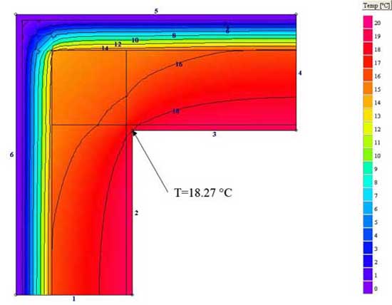
The example shown is a geometric thermal bridge of external wall corner present in the schedule of the UNI EN ISO 14683: 2008 section Corners / C5

Configurazione geometrica secondo UNI 14683

Psi- value calculation with finite element simulation
design values:
Rsi= 0,13 m2K/W Rse= 0,04 m2K/W
d = 0,3 m
U = 0,343 W/(m2K)
R= 2,5 m2K/W thermal insulation
valu from UNI EN ISO 14683: (e = external i = internal)
L2D = 0,71 W/(mK)
ψi = -0,15 W/(mK)
ψe = 0,05 W/(mK)
Through the finite element is calculated a value ψ = 0.034 (W / mK) that more than 30% lower than the value reported in the UNI EN ISO 14683: 2008. The analysis underlines conservative values of linear thermal transmittance ψ given by UNI 14683.
Analysis of thermal bridges
These examples of calculation and simulation of thermal bridges related to real cases performed by finite element method.

external wall-floor section towards unheated attic. Performance of the temperature field (finite element simulation)

external wall-floor section towards unheated attic. Representation value and the direction of heat flux (finite element simulation)

external wall-floor section thermal bridge in correspondence of the balcony. 2D-dimensional calculation of ψ

external wall-floor section thermal bridge in correspondence of the balcony. Temperature field analysis and calculation of min./max. temperature.

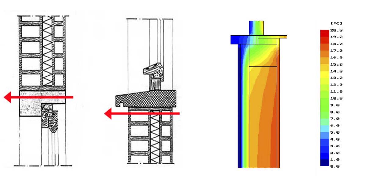
external wall-window section thermal bridge.

external wall-window section thermal bridge. Temperature field analysis and calculation of min./max. surface temperature.